The square-grid
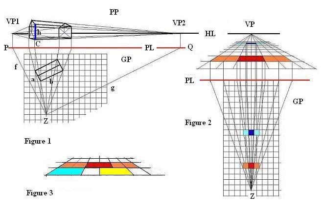
| Figure 1 shows the plan of a building in x,y-map-presentation, and the projection of this building onto a Picture Plane (PP) vertical to the Ground Plane (GP). | ||
| How to create : | ||
| 1. : Draw a line f through Z parallel to a to create P as crossing-point with PL [the line marking the intersection of the Picture Plan (PP) with the Ground Plane (GP)], draw a vertical line to PL through P to create VP1 on the Horizontal Line (HL). Do correspondingly to create VP2. | ||
| 2. : Draw lines from Z through the corner points of the building to create corresponding crossing-points with PL, draw vertical lines to PL through these points to create the lines defining the walls of the building. | ||
| 3: Choose C and h * and draw the outlay of the building. (* C and h are frequently set arbitrarily, an elaborated approach is offered in "the square-grid concept h/d" ) |
Figure 2 shows the central projection of the square grid, with special reference to two sets of red and blue squares.
Figure 3 presents an extract of the projection of the square grid. Note that all colored squares are of equal size.